Table of Contents >> Show >> Hide
- What Is a Retro Oscilloscope Beam Splitter?
- How a Single-Channel Scope Can Pretend to Be Dual-Trace
- The 555 Timer: Tiny Metronome, Big Personality
- Why the Analog CRT Makes This Hack Look So Good
- Beam Splitter vs. Dual-Trace vs. Dual-Beam Oscilloscope
- What You Can Actually Do With It
- Important Limitations Before You Get Too Excited
- Tips for Building a Better Beam Splitter
- Why This Hack Still Matters in the Digital Age
- Real-World Example: Comparing an Audio Filter
- Experience Notes: What It Feels Like to Use One
- Conclusion
There is something wonderfully dramatic about an analog oscilloscope. A digital scope gives you menus, measurements, storage, cursors, decoding, screenshots, and the faint feeling that somewhere inside it lives a tiny accountant. An analog scope gives you a glowing green trace, a warm cathode-ray tube, a knob for nearly everything, and the satisfying sense that you are watching electricity draw its own autobiography in real time.
That is why the idea of a retro oscilloscope beam splitter is so charming. It takes a humble single-channel analog oscilloscope and, with a bit of timing trickery, lets it appear to show two signals at once. It is not magic, although the first time you see two separate waveforms on a one-channel scope, it may feel like someone slipped an extra electron beam into the tube while you were not looking. In reality, the circuit uses time-division multiplexing: it rapidly switches between two input signals and feeds them into the oscilloscope one after the other so quickly that your eyes and the CRT phosphor cooperate to make the result look like two traces.
Think of it as a very fast stage manager. Signal A runs onstage, takes a bow, exits. Signal B runs onstage, takes a bow, exits. This repeats thousands of times per second. The audience, which in this case is you squinting proudly at an old scope, sees a two-character performance.
What Is a Retro Oscilloscope Beam Splitter?
A retro oscilloscope beam splitter is better described as a trace splitter or electronic switch. The phrase “beam splitter” sounds optical, like a prism in a laser lab, but in this hobby-electronics context it refers to a circuit that creates the appearance of two oscilloscope traces from one display channel.
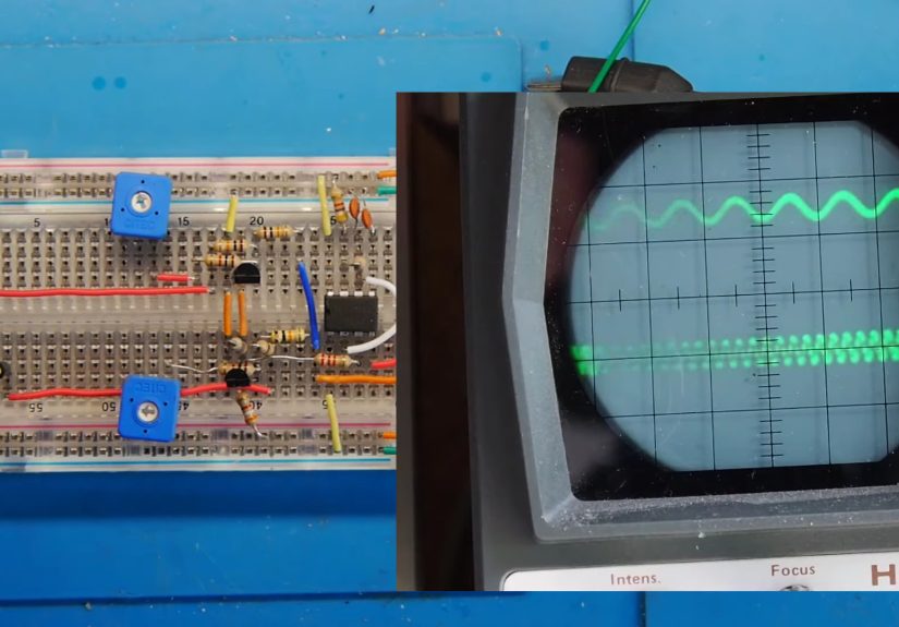
The classic version uses a 555 timer configured as an astable oscillator. In astable mode, the 555 continuously produces a square wave. That square wave then drives a switching stage, often built with complementary transistors or analog switching components. The switch alternates between two signal inputs and sends the selected signal to the oscilloscope input. With the switch running at a few kilohertz, the analog scope draws fragments of each waveform in rapid sequence.
Because a CRT display has persistence, the glowing phosphor does not disappear instantly. Your eyes also integrate visual information over a short period. Together, these effects make the alternating samples look like two continuous traces. The result is delightfully old-school: a single-channel analog oscilloscope suddenly behaves like it has learned a new party trick.
How a Single-Channel Scope Can Pretend to Be Dual-Trace
A true single-channel analog oscilloscope has one vertical input path. It can display one signal at a time. A dual-trace analog oscilloscope, on the other hand, typically uses one electron beam and switches between two channels internally. This is an important distinction: most dual-trace analog scopes are not true dual-beam scopes. They are fast switchers with very nice front panels.
Dual-trace scopes commonly use two display methods: chopped mode and alternate mode. In chopped mode, the scope rapidly switches between channels during one sweep. This is useful for slower signals because both waveforms are built up across the screen at nearly the same time. In alternate mode, the scope draws one channel during one sweep, then the other channel during the next sweep. This works better at faster sweep speeds because the display does not need to be chopped into tiny pieces during each pass.
The retro beam splitter borrows the chopped-mode idea. It does not give the scope a second vertical amplifier, a second calibrated input, or laboratory-grade isolation between channels. Instead, it externally multiplexes two signals into one input. The oscilloscope sees one rapidly changing composite signal. The viewer sees two waveforms separated by an offset. That offset is the secret ingredient that keeps the two traces from sitting on top of each other like confused spaghetti.
The 555 Timer: Tiny Metronome, Big Personality
The 555 timer is one of the most beloved integrated circuits in electronics. It can blink LEDs, generate pulses, act as a timer, create tones, and generally make itself useful in places where a microcontroller would be overkill and a sundial would be underqualified.
In a beam splitter circuit, the 555 usually works as an astable oscillator. It continuously flips its output between high and low. The frequency depends on external resistors and a capacitor. In the retro splitter example, a switching rate around 2.5 kHz is a practical choice because it is fast enough to make the two traces appear stable for many low-frequency signals, yet slow enough that a simple transistor switch can handle the job without needing exotic parts.
The square wave from the 555 controls which signal reaches the oscilloscope. When the output is high, one transistor path conducts and passes signal A. When it is low, the other path conducts and passes signal B. The two input signals are also biased differently so they appear at different vertical positions on the screen. This is why the display shows two separate traces rather than one merged waveform that looks like it had too much coffee.
Why the Analog CRT Makes This Hack Look So Good
Analog oscilloscopes display signals differently from digital oscilloscopes. In a classic analog scope, the input voltage deflects an electron beam vertically while the time base sweeps it horizontally across a phosphor-coated CRT. The waveform is drawn directly by the beam. There is no sampling memory, no LCD pixel grid, and no software interpolation standing between the signal and the glow.
This directness is why analog scopes feel so alive. Intensity, focus, sweep speed, and phosphor persistence all become part of the viewing experience. When the beam splitter switches between signals, the rising and falling transitions of the switching waveform may not appear as crisp vertical lines on the CRT. Instead, the analog display tends to emphasize the stable portions of the two traces, which makes the illusion cleaner.
A digital oscilloscope can also display the multiplexed output, and in some ways it may reveal more of what is actually happening. It can show the switching edges, intermediate levels, and artifacts that the analog CRT visually softens. That is useful for understanding the circuit, but it may be less romantic. The analog scope gives you the stage magic; the digital scope shows you the trap door.
Beam Splitter vs. Dual-Trace vs. Dual-Beam Oscilloscope
These terms are easy to mix up, so let’s untangle them before someone starts arguing with a soldering iron.
Single-Channel Oscilloscope
A single-channel scope has one signal input for vertical display. It is simple, affordable, and still useful for audio work, power-supply troubleshooting, oscillator testing, and general hobby electronics. Its limitation is obvious: comparing two related signals requires either moving the probe back and forth or using an external trick like this beam splitter.
Dual-Trace Oscilloscope
A dual-trace analog oscilloscope usually has two input channels but still uses one electron beam. It switches between channels using chopped or alternate display modes. The switching and scaling are built into the instrument, so the result is cleaner, calibrated, and far more convenient than an external homemade switch.
Dual-Beam Oscilloscope
A true dual-beam oscilloscope is rarer. It uses a special CRT arrangement that can generate two electron beams, sometimes with separate vertical deflection systems. This allows simultaneous display of two signals without time-sharing the same beam. These instruments are historically fascinating, physically bulky, and not something most hobbyists find casually sitting under a thrift-store blanket next to a VCR.
External Retro Beam Splitter
The retro beam splitter is the scrappy cousin. It does not transform your scope into a true dual-trace instrument. It simply multiplexes two signals into one channel. It is not perfect, but it is clever, educational, and charming in the way only a 555-based hack can be.
What You Can Actually Do With It
The practical value depends on your expectations. If you want precision amplitude measurements, clean phase comparisons, high-frequency analysis, or professional debugging, use a real dual-channel scope. If you want to learn, experiment, and squeeze more fun out of an analog instrument, this circuit is a gem.
For example, you can compare the input and output of a small audio amplifier. Feed the original audio signal into input A and the amplified output into input B through suitable attenuation. With the traces vertically offset, you can see gain, distortion, clipping, and phase shift at a glance. It is not a substitute for calibrated measurement, but it is excellent for visual learning.
You can also compare two oscillator outputs, inspect a simple RC filter, or watch the relationship between a square wave and a smoothed capacitor voltage. Students can use the circuit to understand multiplexing, transistor switching, trigger stability, DC offsets, and oscilloscope display persistence. That is a lot of education from a handful of parts.
Important Limitations Before You Get Too Excited
This circuit is fun, but it is not a miracle machine. The first limitation is bandwidth. The switching circuit, transistor characteristics, layout, input impedance, and oscilloscope itself all affect the signal. Fast edges may become rounded, high-frequency content may be distorted, and large signal swings may cause ugly artifacts.
The second limitation is loading. A proper oscilloscope input is usually designed to be high impedance, commonly 1 megohm in parallel with some capacitance. A homemade multiplexer may load the circuit under test more heavily unless it includes proper buffering. Without buffer amplifiers, delicate signals can be pulled around by the splitter. Electronics does not like being manhandled, and small analog signals are especially dramatic about it.
The third limitation is calibration. A real dual-channel oscilloscope has calibrated vertical controls for each channel. A simple beam splitter does not. The vertical spacing and gain may be different for the two inputs depending on component tolerances and biasing. That means you should treat the display as qualitative unless you carefully characterize the circuit.
The fourth limitation is triggering. Since the oscilloscope receives a composite waveform, triggering can become fussy. You may need to trigger from one signal, from the switching waveform, or from an external reference if your scope supports it. Otherwise, the display may drift, roll, or perform interpretive dance.
Tips for Building a Better Beam Splitter
If you want to build your own analog oscilloscope beam splitter, start simple. Use clean power rails, short ground connections, and sensible input protection. Put the circuit in a metal enclosure if possible, or at least keep wiring tidy. At oscilloscope input levels, sloppy layout can turn your project into an accidental antenna.
Add input resistors to reduce the chance of damaging the circuit. Consider using op-amp buffers or dedicated analog switches if you want cleaner results. A CMOS analog multiplexer can provide more predictable switching than a rough transistor arrangement, although it must be chosen carefully for signal range, on-resistance, capacitance, and distortion.
Use adjustable offsets so you can separate the traces neatly. A small potentiometer network can let you position each signal on the screen. This makes the display easier to read and prevents the two waveforms from wrestling each other for the same graticule line.
Also experiment with switching frequency. If it is too slow, the traces flicker or appear segmented. If it is too fast, the switching circuit may introduce more distortion, and your oscilloscope may show a blur or unstable composite. The sweet spot depends on the signals being measured and the scope’s sweep speed.
Why This Hack Still Matters in the Digital Age
Modern digital oscilloscopes are astonishing. Even affordable models can offer multiple channels, automatic measurements, FFT displays, protocol decoding, waveform storage, USB export, and bandwidth that vintage hobby scopes could only dream about. So why bother with a retro beam splitter?
Because understanding old tricks makes you better at new tools. This project teaches time-division multiplexing in a physical, visible way. It demonstrates how display persistence affects perception. It reveals the difference between what a signal is and what an instrument makes easy to see. It also reminds us that clever engineering often comes from constraints.
When you only have one channel, you invent a second one. When you do not have firmware options, you reach for transistors. When your test bench is short on features, you add them with parts from a drawer. That spirit is the soul of hardware hacking.
Real-World Example: Comparing an Audio Filter
Imagine testing a simple RC low-pass filter. You feed a sine wave into the filter and connect the original signal to input A of the beam splitter. Then you connect the filter output to input B. On the oscilloscope, the top trace might show the original waveform, while the lower trace shows the filtered output.
At low frequency, the two sine waves look similar. Increase the frequency, and the output trace begins to shrink. Push higher, and you may also see phase shift: the lower trace lags behind the upper trace. With one channel and a beam splitter, you can now visualize the relationship between input and output without constantly moving the probe back and forth. The setup is imperfect, but for learning electronics, it is wonderfully intuitive.
Experience Notes: What It Feels Like to Use One
Using a retro beam splitter with an analog oscilloscope feels different from using a modern dual-channel digital instrument. The digital scope is polite. It gives you numbers, menus, and a calm rectangular display. The analog setup feels like tuning a small radio station run by electrons.
The first challenge is getting the traces to sit still. You adjust the trigger level. The trace rolls. You nudge the time base. The trace sulks. You adjust the switching frequency. Suddenly, two glowing waveforms appear, and for a moment you feel like you have outsmarted both the oscilloscope and the 1970s. This is a good feeling. It should probably be bottled and sold near solder wick.
The second thing you notice is that the display has personality. On a digital scope, switching artifacts may appear obvious and clinical. On the analog CRT, the phosphor glow gives the traces a softer, more continuous look. Small imperfections become part of the charm. You may see a little brightness variation, a slight fuzz at the edges, or a faint switching ghost between traces. Instead of ruining the experience, these quirks remind you that the display is being painted by a moving beam, not assembled by pixels.
The third lesson is humility. It is tempting to believe the two traces are fully independent, but they are not. If the circuit lacks proper buffering, one input may influence the other. If the offsets are poorly chosen, the traces overlap. If the switching rate is wrong, the display becomes confusing. If your grounding is careless, noise appears like an uninvited raccoon at a picnic. This is where the project becomes more than a novelty. It teaches measurement discipline.
Good probing matters. Short ground leads matter. Signal amplitude matters. Input impedance matters. The trigger source matters. The beam splitter is fun because it works, but it is educational because it does not work perfectly unless you respect the details.
One of the most satisfying uses is audio troubleshooting. Feed a sine wave into a small amplifier, route the input and output through the splitter, and watch the gain change as you adjust the circuit. Push the amplifier too hard, and the output trace clips. Change a coupling capacitor, and the low-frequency response shifts. Add a tone control, and the waveform tells you what your ears will soon confirm. It is hands-on, visual, and slightly theatrical.
Another enjoyable experiment is comparing a square wave before and after an RC network. The original trace has sharp edges. The filtered trace rises and falls slowly, showing the capacitor charging and discharging. On paper, that is an exponential curve. On the screen, it looks like the circuit is breathing. For beginners, that visual connection can make theory click faster than another page of equations.
The biggest practical lesson is knowing when not to trust the setup. A retro oscilloscope beam splitter is excellent for demonstrations, relative comparisons, and low-frequency experiments. It is not the right tool for precision timing, high-speed digital edges, or measurements where safety and accuracy matter. If you are working on mains-powered equipment, high voltage, medical electronics, or anything expensive enough to make you whisper “please no” before turning it on, use proper isolated equipment and a real multi-channel scope.
Still, for bench learning, vintage repair, audio tinkering, oscillator experiments, and rainy-afternoon electronics joy, this little circuit earns its place. It takes an old single-channel scope and gives it a second voice. Not a perfect voice. Not a calibrated voice. More like a charming garage-band harmony. But sometimes that is exactly what makes electronics fun.
Conclusion
The retro analog oscilloscope beam splitter is a clever reminder that engineering is often about making the most of what you have. By using a 555 timer, a switching stage, and the natural persistence of a CRT display, a single-channel analog scope can appear to show two waveforms at once. It is not the same as owning a true dual-trace or dual-beam oscilloscope, but it is a brilliant teaching tool and a satisfying weekend project.
More importantly, it captures the spirit of analog electronics: direct, visible, imperfect, and endlessly hackable. In a world of touchscreen instruments and automated measurements, there is still joy in watching a green trace glow across glass and knowing that a handful of parts just doubled your oscilloscope fun.
Note: This article is written in original American English and synthesized from real technical information about analog oscilloscopes, 555 timer astable circuits, dual-trace display modes, CRT persistence, triggering, and analog multiplexing.