Table of Contents >> Show >> Hide
- What Is Cogging Torque in a Brushless Motor?
- Why Hobby Brushless Motors Struggle at Low Speed
- How an Anti-Cogging Algorithm Works
- Why Anti-Cogging Makes Cheap Motors Feel Expensive
- Best Applications for Anti-Cogging in Hobby Projects
- Anti-Cogging vs. Gearboxes: Which Is Better?
- What You Need to Try Anti-Cogging
- Calibration: The Step You Should Not Rush
- FOC and Anti-Cogging: Better Together
- Realistic Expectations: What Anti-Cogging Can and Cannot Do
- Specific Example: A DIY Direct-Drive Drawing Arm
- How to Get Better Results From Your Setup
- The Future of Hobby Brushless Motor Control
- Hands-On Experience: What Anti-Cogging Feels Like on the Bench
- Conclusion
Brushless motors are the tiny overachievers of the hobby world. They fling drones into the sky, push RC cars across parking lots like caffeinated squirrels, and give robot arms the kind of torque that makes stepper motors glance nervously at the exit. But when you ask a typical hobby brushless motor to move slowly, smoothly, and precisely, it may suddenly act less like a precision actuator and more like a shopping cart with one square wheel.
That annoying bump-bump-bump feeling is often caused by cogging torque. It is the magnetic tug-of-war between the permanent magnets in the rotor and the teeth or slots in the stator. At high speed, the effect can disappear into the blur. At low speed, especially in direct-drive robotics, gimbals, camera sliders, haptic devices, and small CNC-style mechanisms, cogging can become painfully obvious.
An anti-cogging algorithm is one of the smartest software tricks for making inexpensive hobby brushless motors behave like much more refined motion-control hardware. Instead of replacing the motor, adding a gearbox, or pretending the jitter is “character,” the controller learns the motor’s torque ripple pattern and applies compensation at the right rotor positions. The result is smoother low-speed motion, better position holding, cleaner torque control, and fewer “why is my robot arm doing jazz hands?” moments.
What Is Cogging Torque in a Brushless Motor?
Cogging torque is a position-dependent torque variation that happens even when no current is intentionally producing motion. In a slotted brushless DC motor, the rotor magnets naturally prefer certain alignments with the stator teeth. When you turn the motor shaft by hand, you may feel tiny magnetic notches. That is cogging.
In hobby motors, cogging is not automatically a sign of a bad motor. Many affordable outrunners and inrunners are built for power density, speed, cooling, and cost. A drone motor that spins at thousands of RPM does not need to creep smoothly through one degree of rotation like a laboratory-grade torque motor. So manufacturers often optimize for thrust, efficiency, weight, and pricenot silky direct-drive positioning.
Cogging Torque vs. Torque Ripple
People often use the terms together, but they are not exactly the same. Cogging torque comes from the magnetic geometry of the motor, especially the interaction between rotor magnets and stator slots. Torque ripple is the broader category of unwanted torque variation during operation. Torque ripple can come from cogging, imperfect commutation, current-sensing errors, winding imbalance, controller timing, bus-voltage ripple, or mechanical misalignment.
In plain English: cogging is one flavor of torque ripple. It is the flavor that makes a motor feel like it has invisible detents. Unfortunately, it is also the flavor that shows up exactly when hobbyists want graceful slow movement.
Why Hobby Brushless Motors Struggle at Low Speed
Hobby brushless motors are wonderful, but many were designed for propellers, wheels, fans, and high-speed loads. When used in robotics or precision motion systems, they are being asked to perform outside their comfort zone. It is like hiring a sprinter to do ballet. The horsepower is there. The toe-pointing may need work.
At low speed, several issues become more visible:
- Cogging torque: The motor prefers some rotor positions over others.
- Commutation ripple: Basic six-step control can create uneven torque delivery.
- Insufficient rotor feedback: Smooth control usually needs a good encoder or magnetic angle sensor.
- Poor current control: Without accurate phase-current measurement, torque can wander.
- Loose mechanics: Belt stretch, backlash, shaft wobble, and flexible mounts can exaggerate motor roughness.
This is where modern control methods such as field-oriented control and anti-cogging compensation become useful. FOC helps align phase currents with the rotor field so the motor produces smoother torque. Anti-cogging adds another layer: it corrects a motor-specific repeating torque pattern that FOC alone may not erase.
How an Anti-Cogging Algorithm Works
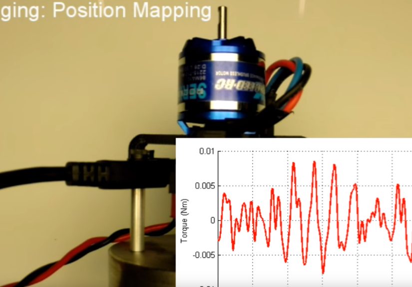
An anti-cogging algorithm usually works in two stages: mapping and compensation. First, the controller slowly moves the motor through its rotation and records how much extra torque or current is needed at many rotor positions. Then, during normal operation, it uses that stored map to apply a feedforward correction.
Think of it like driving down a road full of tiny hills. A basic controller only reacts after the car slows down or speeds up. Anti-cogging gives the controller a map of the hills in advance. Before the motor reaches a magnetic “uphill” spot, the controller adds a little push. Before it reaches a “downhill” spot, it backs off. The motor feels smoother because the controller is no longer surprised.
The Lookup Table Method
The most common hobby-friendly approach uses a lookup table. The controller divides one mechanical or electrical rotation into many positions. At each position, it stores a correction value. That value may represent extra q-axis current, torque feedforward, or a voltage offset depending on the firmware and hardware.
During operation, the controller reads the rotor position from an encoder or sensor, finds the matching entry in the table, and blends that correction into the motor command. Some implementations interpolate between table entries for smoother behavior.
Why Position Feedback Matters
Anti-cogging depends on knowing where the rotor is. A poor sensor can make the correction late, noisy, or completely wrong. For best results, builders often use magnetic encoders, optical encoders, or high-resolution absolute position sensors. Hall sensors can be useful for commutation, but they are usually too coarse for refined anti-cogging compensation.
Sensor alignment also matters. If the angle sensor is offset, slipping, mounted off-center, or affected by magnetic interference, the controller may compensate the wrong location. That can turn an anti-cogging algorithm into a pro-cogging algorithm, which is not a feature anyone should advertise.
Why Anti-Cogging Makes Cheap Motors Feel Expensive
High-end motors often reduce cogging through mechanical design: skewed stator slots, optimized magnet shapes, slotless construction, careful winding patterns, and tight manufacturing tolerances. Those methods work, but they cost money. Hobby motors are cheaper partly because they do not always include those refinements.
Anti-cogging is attractive because it attacks the problem in software. It does not magically change the steel, magnets, bearings, or winding geometry. But it can reduce the effect that the user feels, especially in closed-loop control systems.
For many hobby projects, that is the whole game. If the motor holds position better, tracks slowly without jerking, and feels smoother under hand-guided motion, the project improves immediately. A robot joint becomes less twitchy. A camera rig stops micro-stuttering. A haptic knob feels premium instead of crunchy. A low-cost direct-drive actuator suddenly looks like it has been attending finishing school.
Best Applications for Anti-Cogging in Hobby Projects
Direct-Drive Robot Arms
Direct-drive robot joints are one of the best use cases. Without a gearbox, every motor imperfection goes straight to the output. Anti-cogging can help the joint move smoothly through small angles, hold a commanded pose, and follow slow trajectories without pulsing.
Camera Gimbals and Sliders
Video equipment is brutally honest. A tiny motor twitch can become a visible bump in footage. Anti-cogging can help brushless gimbals and sliders achieve more graceful starts, stops, and creeping movements.
Haptic Interfaces
Knobs, force-feedback devices, steering wheels, and training simulators benefit from smooth torque. Cogging can ruin the illusion of a virtual spring, detent, or texture. Compensation helps the controller create intentional sensations instead of fighting accidental ones.
Low-Speed RC and Rover Platforms
RC vehicles usually hide motor roughness with speed, gearing, and tire compliance. But crawlers, rovers, and small autonomous vehicles often need controlled low-speed movement. Anti-cogging can help reduce jerk when paired with proper gearing, current control, and feedback.
DIY CNC, Plotters, and Drawing Robots
For lightweight machines, brushless motors can be tempting alternatives to steppers. Anti-cogging can improve low-speed path tracking, especially in experimental drawing robots or polar plotters where smooth curves matter.
Anti-Cogging vs. Gearboxes: Which Is Better?
A gearbox can hide cogging by multiplying torque and increasing effective output resolution. It also brings its own baggage: backlash, friction, noise, weight, cost, maintenance, and reduced backdrivability. Anti-cogging keeps the direct-drive feel while improving smoothness.
That does not mean anti-cogging replaces gearboxes everywhere. If your project needs high torque at low current, a gearbox is still useful. If you need backdrivable force control, quiet motion, and minimal mechanical complexity, anti-cogging plus FOC can be a fantastic path.
The practical answer is usually this: use mechanical design to solve big problems, and use software compensation to polish what remains. A motor controller is not a wizard, but with a good encoder and a clean calibration routine, it can wear a surprisingly convincing hat.
What You Need to Try Anti-Cogging
To experiment with anti-cogging on hobby brushless motors, you typically need:
- A brushless motor suitable for closed-loop control
- A motor controller that supports FOC or torque control
- A position sensor with enough resolution
- Stable motor mounting
- A safe power supply with current limits
- Firmware or software that supports cogging compensation
- Patience, because calibration is where optimism goes to be tested
Open-source and hobby-friendly ecosystems have made this much easier than it used to be. Controllers and libraries such as ODrive-style systems, VESC-based platforms, and SimpleFOC-inspired projects have helped bring advanced motor-control concepts into garages, labs, classrooms, and slightly cluttered workbenches everywhere.
Calibration: The Step You Should Not Rush
Anti-cogging is only as good as its calibration. The motor should be unloaded or loaded consistently during mapping, depending on the implementation. The shaft should move freely, the sensor should be stable, and the control gains should be sane before calibration begins.
If the motor vibrates, stalls, or oscillates during calibration, do not blame the algorithm immediately. Check the basics first: encoder direction, pole-pair count, current limits, phase wiring, sensor mounting, power supply capacity, and PID gains. Many “software problems” in motor control are actually wiring problems wearing a fake mustache.
Common Calibration Mistakes
- Using a loose sensor magnet: If the magnet shifts, your cogging map becomes fiction.
- Mapping with mechanical drag: Bearing drag or cable tension can pollute the correction table.
- Skipping motor identification: Resistance, inductance, pole pairs, and encoder offset should be known first.
- Expecting miracles from low-resolution feedback: The controller cannot compensate what it cannot measure.
- Overcompensating: Too much correction can create new ripple instead of canceling the old ripple.
FOC and Anti-Cogging: Better Together
Field-oriented control is often the foundation for smooth brushless motor behavior. It transforms three-phase motor currents into a rotating reference frame, allowing the controller to manage torque-producing current more directly. In practice, FOC helps a BLDC or PMSM behave less like a choppy switched device and more like a controlled torque source.
Anti-cogging builds on that foundation. FOC says, “I know how to produce torque efficiently.” Anti-cogging says, “I also know where this particular motor likes to misbehave.” Together, they can deliver slow movement that feels controlled rather than lumpy.
This distinction matters because some builders assume FOC automatically eliminates cogging. It may reduce commutation-related torque ripple, but cogging torque is tied to motor geometry. A separate compensation map is often needed if the goal is very smooth direct-drive motion.
Realistic Expectations: What Anti-Cogging Can and Cannot Do
Anti-cogging can make a dramatic difference, but it is not a universal cure. It works best when the cogging pattern is repeatable and tied to rotor position. It struggles when the disturbance changes randomly, comes from a loose mechanical part, or depends heavily on load direction.
It also cannot fix a motor that is wildly undersized, overheated, poorly mounted, or controlled by noisy electronics. If the motor shaft is wobbling like a spoon in a garbage disposal, no lookup table will restore dignity.
Still, when the hardware is fundamentally sound, anti-cogging can be one of the highest-value upgrades in a hobby brushless setup. It costs little in extra hardware if you already have position feedback, and it can unlock performance that would otherwise require a much more expensive motor.
Specific Example: A DIY Direct-Drive Drawing Arm
Imagine a small two-link drawing robot using hobby outrunner motors at each joint. Without anti-cogging, the pen moves in tiny pulses at slow speed. Curves look slightly segmented. Diagonal lines have microscopic wiggles. The robot can draw, but its handwriting suggests it had three espressos and a family emergency.
Now add a magnetic encoder to each joint, tune FOC current control, and run an anti-cogging calibration routine. The controller maps the torque needed at each rotor angle, then adds compensation while following the drawing path. The pen motion becomes smoother, especially during slow arcs and direction changes. The motors still have the same magnets and stator teeth, but the controller is now actively canceling their worst habits.
This is the beauty of the anti-cogging algorithm: it turns known imperfection into predictable data. Once the controller knows the pattern, it can work around it.
How to Get Better Results From Your Setup
Use a Good Encoder
Choose a sensor with enough resolution for the motion you care about. For smooth direct-drive control, more accurate rotor position data usually means better compensation.
Keep the Mechanics Rigid
A flexible mount can make the motor look worse than it is. Secure the motor, encoder, and load so the calibration map reflects the motornot the table wobbling under it.
Tune the Controller Before Mapping
Anti-cogging should not be used as a bandage for bad control gains. Get stable torque, velocity, or position behavior first. Then use compensation to refine smoothness.
Test Slowly and Safely
Start with conservative current limits. A brushless motor under closed-loop control can move suddenly if the configuration is wrong. Keep fingers, wires, and coffee cups out of the danger zone.
Recalibrate When Hardware Changes
If you change the encoder mount, motor, magnet, shaft coupling, or major load condition, the old cogging map may no longer be accurate. Recalibration is cheaper than chasing ghosts.
The Future of Hobby Brushless Motor Control
Hobby motor control has moved quickly from simple ESCs to sophisticated embedded drives. Features that once belonged mainly in industrial servo drives are now appearing in open-source firmware, maker boards, and affordable robotics controllers. Anti-cogging is part of that shift.
As microcontrollers get faster, current sensing improves, and magnetic encoders become cheaper, more hobbyists will treat brushless motors as precision actuators rather than just spinning machines. That opens the door to affordable robot arms, quiet desktop automation, advanced camera tools, educational haptics, and experimental machines that feel smoother than their price tags suggest.
Hands-On Experience: What Anti-Cogging Feels Like on the Bench
The first time you test anti-cogging on a hobby brushless motor, the difference may feel almost suspicious. Before compensation, turning the shaft by hand reveals the classic magnetic stepping sensation. It is not harsh, but it is there: a series of tiny preferred positions. Under closed-loop control, the motor may hold position well enough, but slow commands expose little hesitations. Move from 0 to 10 degrees over several seconds and the rotor may creep, pause, tug forward, and then settle. Technically, it works. Emotionally, it feels like the motor is arguing with you.
After calibration, the same motor can feel calmer. Slow position moves become more continuous. A direct-drive knob feels less grainy. A small robot joint becomes easier to command through delicate movements. You may still feel bearing friction, load imbalance, belt tension, or encoder noise, but the repeating magnetic lumpiness is reduced. It is the difference between dragging a chair across gravel and rolling it across a clean workshop floor. Neither is levitation, but one is much less embarrassing.
In practical projects, the most noticeable improvement often appears at near-zero speed. For example, a camera slider may already look fine during fast travel, but when it performs a dramatic slow push-in, cogging becomes visible as micro-jerk. Anti-cogging helps smooth that low-speed crawl. In a haptic controller, the benefit is even more obvious because your hand is extremely sensitive to torque ripple. When the correction is tuned well, the motor stops announcing every stator tooth through your fingertips.
One useful bench test is to command the motor to move slowly through one full rotation while lightly touching the output shaft or attached arm. Do this before and after compensation. Before anti-cogging, you may feel periodic pulses. Afterward, those pulses should shrink. Another test is position holding near several different angles. If the motor previously hummed or nudged itself into certain magnetic valleys, compensation can reduce the tendency to “prefer” those positions.
The biggest lesson from real experimentation is that anti-cogging rewards careful setup. A clean encoder mount matters. A centered magnet matters. Reasonable current limits matter. If the motor is mounted to a flexible 3D-printed bracket that resonates like a tiny banjo, the algorithm cannot save the day alone. Likewise, if the power supply sags or the control loop is unstable, compensation may make the system feel stranger rather than smoother.
It also helps to treat anti-cogging as the final seasoning, not the entire recipe. Start with the mechanical system. Make sure the shaft spins freely. Confirm the pole-pair count. Verify encoder direction. Tune FOC. Tune velocity and position loops. Then run anti-cogging calibration. When done in that order, the algorithm feels like a clever upgrade. When done backward, it feels like trying to fix soup by yelling at the spoon.
For hobbyists, the real joy is that this technique can transform inexpensive motors into surprisingly refined actuators. No, a budget outrunner will not become a medical-grade frameless torque motor overnight. But it can become smoother, more useful, and much more pleasant to control. That is exactly the kind of upgrade makers love: a little math, a little calibration, and suddenly the hardware you already own behaves like it read a self-improvement book.
Conclusion
An anti-cogging algorithm brings out the best in hobby brushless motors by teaching the controller to anticipate and cancel repeatable torque disturbances. Instead of accepting low-speed jitter as the unavoidable cost of affordable hardware, builders can map the motor’s cogging profile and apply position-based compensation. The result is smoother direct-drive motion, better low-speed control, improved haptic feel, and more professional behavior from motors that were never originally designed to act like precision servos.
For drones and RC speed machines, cogging may barely matter. For robot arms, camera rigs, haptic knobs, desktop automation, and experimental actuators, it can make or break the experience. Anti-cogging is not magic, but it is very good engineering: measure the flaw, store the pattern, and correct it at exactly the right time. That is how a humble hobby brushless motor gets promoted from “spins fast” to “moves beautifully.”
Note: This article is intended for educational and hobby robotics use. Always test brushless motors with safe current limits, secure mounting, and proper protection before running closed-loop motion experiments.